

A panel can leave the drilling station looking acceptable and still fail at assembly. A hinge cup chips, a dowel will not enter, or face and edge holes miss each other. Changing the drill bit may help—but it is not a complete diagnosis.
Poor hole quality can start with the tool, settings, dust extraction, panel support, machine calibration or the digital job. The fastest recovery comes from identifying the defect, checking simple causes first and verifying the correction on repeated parts.
Quick Answer: What Causes Poor CNC-Drilled Holes?
Poor CNC drilling quality is usually caused by a worn or unsuitable drill, excessive tool runout, incorrect feed and spindle settings, blocked chip evacuation, panel movement, material variation, machine misalignment, or incorrect program and reference data. Diagnose the symptom first; then check the job data, panel, tool, settings, clamping and calibration in that order.
Start With the Defect, Not the Parameter Screen
Record whether the defect is on the entry face, exit face, panel edge or inside the hole before changing anything.
| Visible defect | Likely causes | First check |
|---|---|---|
| Chipped entry or exit | Dull tool, unsuitable geometry, weak support | Compare both faces and inspect the cutting edge |
| Oversized or oval hole | Runout, loose holder, worn drill, panel movement | Measure the tool and check its seating |
| Variable hole depth | Panel bow, thickness variation, wrong offset, dust buildup | Measure panel thickness and confirm the Z reference |
| Consistent position error | Wrong datum or machine calibration | Compare the program origin with the finished panel |
| Random position error | Slippage, unstable support, wrong job loaded | Inspect clamp marks and production records |
| Rough or dark hole wall | Dull edge, poor chip removal, unsuitable feed/RPM | Examine the tool, dust and cutting sound |
| Face and edge holes do not meet | Finished-size error, gripping or drill-bank alignment | Run a controlled test panel |
Eight Causes of Poor Hole Quality in CNC Drilling
1. The Drill Is Worn, Damaged or Wrong for the Panel
A dull edge rubs and compresses fibres instead of cutting cleanly. Signs include fuzzy walls, breakout, heat marks and gradual dimensional drift. A sharp drill may still be unsuitable for a laminated surface, blind hole or through-hole.
Track holes processed by material, inspect the edge and compare a suspect drill with a known-good one. If replacement does not restore quality, stop changing tools and continue the diagnosis.
2. Feed and Spindle Speed Do Not Match the Material
There is no universal setting for MDF, particleboard, plywood and melamine-faced panels. Excessive feed can increase thrust and breakout; a poor speed/feed combination creates rubbing, heat or unstable cutting.
A peer-reviewed MDF study found that, under its test conditions, delamination decreased with higher cutting velocity and increased with feed rate. Treat this as direction, not a universal recipe: geometry, diameter, density and machine stiffness change the result. Alter one variable at a time and record it.
3. Dust and Chips Are Not Leaving the Hole
Packed dust increases friction, scratches the wall and can prevent a blind hole from reaching depth. In dry woodworking, effective extraction and clear flutes matter more than metalworking coolant advice.
Check rejected holes, extraction ducts, brushes and the lower drilling area. Quality that worsens through a batch often suggests wear or evacuation loss, not a coordinate error.
4. The Panel Moves or Lacks Support
If the board shifts, position and roundness can change together. On small, narrow or bowed parts, inspect clamp marks, reference surfaces, gripper pressure and support near through-hole exits.
Air-flotation support and controlled gripping help, but cannot stabilize severely bowed or incorrectly sized panels.
5. Panel Properties Have Changed
Boards with the same nominal thickness may cut differently. MDF density, particleboard cores, plywood layers and coatings affect force and edge behaviour. A 2025 review links wood-panel tool wear and delamination to panel type and density, drill material, cutting conditions and machine–holder–tool stiffness.
If defects begin with a new batch, test old and new material with the same tool and program. Measure actual thickness and flatness.
6. Tool Runout or Mechanical Alignment Is Outside Control
Runout makes the drill orbit around the intended centre, producing oversized, oval or tapered holes and uneven edge wear. Causes include a dirty interface, poor installation, damaged holder, worn bearing or drill-bank misalignment.
Check calibration when several drills show the same directional error, face and edge holes repeatedly miss, or a known-good tool produces the defect. Parameter changes cannot correct a mechanical reference error.
7. The Datum or Finished Panel Size Is Wrong
A clean, round hole can still be misplaced. If the panel is oversize, the wrong edge is referenced or edging thickness is omitted, every hole can be correct in machine coordinates and wrong at assembly.
Compare the CAD/CAM datum with the finished panel, including orientation and edging allowance. A batch-wide fixed offset suggests data or calibration; occasional offsets suggest handling, scanning or support.
8. The Barcode or Machining Program Is Wrong
Automation repeats bad instructions consistently. An old barcode revision, incorrect mirror, wrong tool number or post-processing error can create perfect holes in the wrong places.
Confirm the panel ID, revision, tool mapping and previewed path before touching the machine.
A Practical Troubleshooting Order
Use the following sequence to avoid changing several variables at once:
- Stop and isolate affected panels before they reach edging or assembly.
- Mark the defect type, face, tool number, program and time it occurred.
- Decide whether the error is systematic or random. Check whether it affects every panel, one material, one drill or one shift.
- Verify the barcode, program revision, datum, mirror direction and finished panel dimensions.
- Inspect the drill, holder, flutes, extraction and panel support.
- Compare feed and RPM with the last approved setting for that exact material and tool.
- If the problem remains, check runout, gripper repeatability and drill-bank or axis calibration.
- Process several consecutive representative panels and record diameter, depth, position and hardware fit before restarting the batch.
One acceptable panel is not proof of stability. A test of 30 consecutive panels provides 30 repeatability observations—not a universal accuracy claim. Record the board, tool, settings, measuring instrument and date.
When a Six-Sided CNC Drilling Machine Helps
A dedicated cnc 6-sided drilling machine reduces risks from manual flipping and separate setups. Top, bottom and horizontal operations follow one digital job while grippers retain the panel reference. Barcode loading reduces manual selection if scan exceptions are controlled.
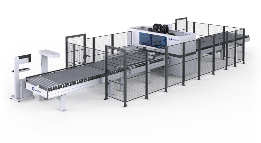
The Caelus D5S CNC 6-Sided Drilling Center accepts panels 200–2,800 mm long, 50–1,220 mm wide and 9–60 mm thick, with published permitted unevenness of no more than 0.3 mm. Its drill block supports diameters to 35 mm and drilling depth to 45 mm. These are equipment specifications, not guaranteed finished-hole tolerances; results still depend on tooling, material, data and maintenance.
For connected production, the D5A CNC Automated 6-Sided Drilling Center combines 2+1 drilling heads, 53 tools, 600 mm barcode scanning and CAD/CAM, DXF, MPR and XML support. Its exception logic can return a misread panel or reject and flag an abnormal one. Preventing the wrong program is part of hole-quality control.
No woodworking CNC machine can compensate for inaccurate cutting, uncontrolled panel bow, unsuitable tooling or incorrect data. Equipment should strengthen a controlled process, not replace one.
Preventing the Problem From Returning
Require a first-piece check after any tool, material, program, edging allowance or maintenance change. Each shift, confirm the barcode revision, tool, extraction and hardware fit. Periodically inspect holders, grippers, references and a standard face-to-edge pattern.
Track assembly results as well as hole diameter. Useful measures include first-pass assembly yield, defects by material, tool life by holes processed, and repeated position/depth readings under stated test conditions.
FAQ
Q1. Why Do CNC-Drilled Holes Chip Around the Edge?
A: Check drill condition and geometry, feed, exit support, coating behaviour and packed dust. Compare entry and exit damage first.
Q2. Why Are Holes Larger Than Programmed?
A: Check drill diameter, seating, runout, holder and panel movement. If several tools show the same error, inspect alignment.
Q3. Why Does Hole Depth Vary Between Panels?
A: Measure real panel thickness and bow, verify tool-length compensation and Z reference, and check whether dust is compacting in blind holes.
Q4. Can a Six-Sided Drill Eliminate Hole-Quality Problems?
A: It can reduce repositioning and manual handling errors, but it cannot correct poor tools, wrong programs, inaccurate upstream sizing or uncontrolled material variation.
Q5. What Should Be Tested Before Buying a CNC Drilling Machine?
A: Use your own materials, smallest and largest parts, blind and through holes, face-to-edge patterns, mixed barcodes and real hardware. Agree on measurement methods and compare repeated results, not maximum speed alone.
Conclusion
Poor hole quality is best treated as a process signal. Start with the visible symptom, separate random from systematic errors, and check data and material before changing parameters. When repeated handling, inconsistent referencing or limited exception control remains the bottleneck, a sample-panel test can show whether six-sided drilling is the right next step for your production.